From Cables to Connections: Decoding the Data Link Layer

When we talk about the internet, we often think about massive data centers, undersea cables, and cloud servers scattered around the world. But before any of that comes into play, every single piece of data takes a tiny local trip from your device to the next one directly connected to it.
That small, invisible hop is managed by the Data Link Layer, also known as Layer 2 in the OSI model. This layer is responsible for the reliable, direct transfer of data between two adjacent network devices, often called node-to-node delivery.

At this local level, the essential functions of networking are performed:
Data is packaged (Framing).
Physical addresses are managed (MAC Addressing).
Rules are enforced for sharing the communication medium (Medium Access Control).
Errors introduced during transmission are detected and corrected.
We will be breaking down the core functionalities of data link layer in this blog.
1. Link Layer Fundamentals: Framing and Addressing
To send data over any physical medium (like Ethernet cables or Wi-Fi signals), Link Layer needs to organize and label it properly.
1.1. Data Framing
Data from the Network Layer (IP packets) is wrapped into a structure called a Frame before being transmitted, and that process is called Framing.

A typical frame has three parts:
Header: Control info like the source and destination physical (MAC) addresses.
Payload: The actual data being sent (for example, an IP packet).
Trailer: Error-checking bits to confirm that the frame wasn’t corrupted.
This frame is the complete unit handled by the Data Link Layer.
1.2. Physical Addressing (MAC Addresses)
Each device connected to a network has a unique hardware address called a MAC address. It’s a 48-bit hexadecimal notation identifier burned into the device’s Network Interface Card (NIC). Example: 00:1A:92:B0:4C:29
Used for local communication only (within the same LAN ).
Helps ensure that data sent reaches the correct device, even if many devices share the same medium.
You can quickly check the MAC address of your device by running this command on terminal (Mac/Linux) or CMD/Powershell (Windows) :
a. For Windows: ipconfig /all
b. For Mac/Linux: ip addr or ifconfig
On running ip addr, you’ll see multiple interfaces(physical/virtual) in your device. And, on each interface, you will see the MAC address of your device on that interface. Look at the highlighted section for MAC address in wlp0s20f3 interface in this example.

2. Ensuring Data Integrity: Error Detection Techniques
During transmission, data can get corrupted due to electrical interference or noise.
That’s why the Link Layer adds error-checking bits to frames to detect (and sometimes correct) errors.
2.1. Parity Checking
Parity Checking is the simplest method. It adds one extra bit (the parity bit) to your data.
In even parity, the total number of 1s (including the parity bit) must be even.
In odd parity, it must be odd.

If the receiver counts the wrong number of 1s, it knows something went wrong. However, parity can only detect an odd number of bit errors; if two bits flip, Parity check fails to detect the error.
2.2. Checksums
A checksum is a more advanced Error Detection method. Here, all data bytes are added up, and the total (or a portion of it) is attached as a checksum value. When the receiver gets the data, it performs the same calculation. If the result doesn’t match, it’s a clear sign that the data was corrupted and data gets discarded.
Below diagram is a sample example of checksum verification.

2.3. Cyclic Redundancy Check (CRC)
The Cyclic Redundancy Check, or CRC is the most powerful and widely used error-detection technique in Link Layer.
It treats data as a long binary number and divides it by a specific polynomial. The remainder from this division becomes the CRC value, which is added to the frame’s trailer. At the destination, the same calculation is repeated. If the remainder doesn’t match, the frame is known to be corrupted and is discarded.
Ethernet, Wi-Fi, and USB all rely on CRC because it can detect burst errors (where several bits flip together) with high reliability.

3. Medium Access Control (MAC) Protocols
When many devices share a single communication channel, chaos can occur if everyone tries to send data at once. The Link Layer solves this problem with Medium Access Control (MAC) protocols, which define who gets to talk and when.
3.1. Random Access Protocols
In these protocols, nodes transmit without strict central coordination; collisions are possible and must be managed.
3.1.1. CSMA/CD (Collision Detection)

This protocol is used in wired Ethernet, CSMA/CD works like people talking in a meeting:
Everyone listens before speaking (Carrier Sense).
If the channel is free, they talk.
If a collision is detected during transmission, the node immediately stops, broadcasts a jam signal, and waits a random time before retrying.
This method worked perfectly in early shared Ethernet networks but isn’t needed in modern switched Ethernet (since each link is full-duplex).
3.1.2. CSMA/CA (Collision Avoidance)

This protocol is used in Wi-Fi networks because collision detection is difficult in the air, the protocol attempts to avoid collisions proactively. Here, nodes listen, and if the channel is busy, transmission is deferred. Signals like RTS/CTS (Request to Send/Clear to Send) are often used to reserve the medium before transmission.
3.2. Taking Turns Protocols
These protocols introduce order and are used in environments where guaranteed bandwidth or predictable performance is required.
3.2.1. Polling
A master device (controller) asks each connected device, one by one, whether it has data to send. It is efficient and collision-free ideally, but slower when many devices are idle.
3.2.2. Token Passing
A special frame called a token circulates between devices.Only the one holding the token can send data which ensures zero collisions in the network.

4. Advanced Link Layer Architectures
The core Link Layer ideas have evolved over time to support larger, faster, and more flexible networks. Let’s look at three key developments.
4.1. Link Virtualization (VLANs)
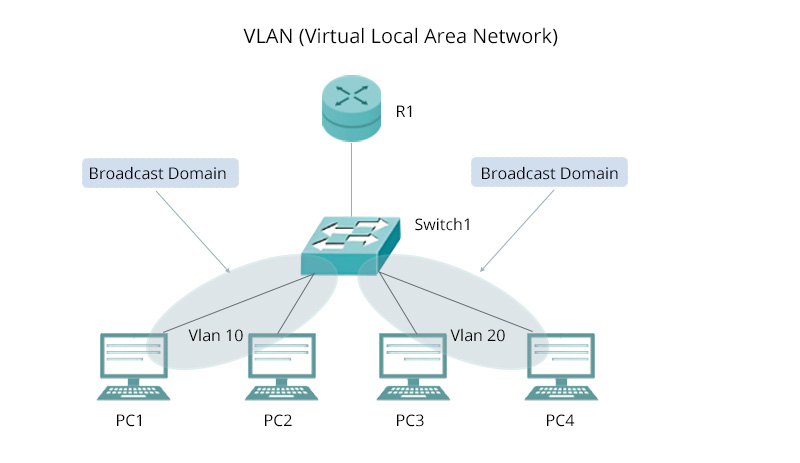
Link Virtualization is the process of decoupling the logical network topology from the physical one. The most common example is the VLAN (Virtual Local Area Network).
VLANs allow a single physical network switch to be logically segmented into multiple independent broadcast domains. This is critical for improving network security and management.
4.2. Multiprotocol Label Switching (MPLS)
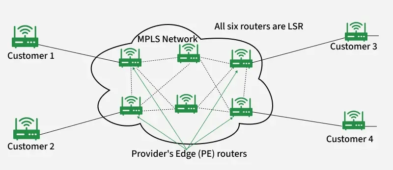
MPLS is a high-performance forwarding technique often seen as residing between Layer 2 and Layer 3, used primarily by ISPs. Instead of reading long IP headers, routers just look at the label to decide where to forward the packet, making it faster and more predictable.
How it Works ?
It works by inserting a short, fixed-length label onto the data unit.
Core routers then forward the data based solely on this simple label, avoiding the time consuming process of inspecting the complex Network Layer header.
MPLS is used to create highly efficient express paths for traffic and building VPNs.
4.3. Data Over Cable Systems (DOCSIS)

DOCSIS (Data Over Cable Service Interface Specification) is the Link Layer standard that enables high-speed data transmission over existing coaxial cable TV systems.
It defines how your cable modem talks with your provider’s CMTS (Cable Modem Termination System), managing shared bandwidth and preventing interference.Without DOCSIS, cable Internet wouldn’t exist as we know it !
5. Conclusion
Although we rarely think about it, Layer 2 is where reliable networking begins. It ensures that every bit of data safely travels from one neighbor to another before the higher layers take over for global communication.
Key takeaways about the Link Layer include:
Its primary data unit is the Frame.
It uses MAC addresses for local, node-to-node delivery within a network.
CRC is the dominant technique used for reliable error detection.
CSMA protocols (CD for wired, CA for wireless) manage access to the shared medium.
Advanced techniques like VLANs and MPLS are used for modern network flexibility and speed.
I hope this post gave you a clear and friendly peek into how Link Layer works in Internet. Thank you !
Connect with me on:

